Earle provides a series of photographs for the Thunderbird build, showing his recommended parts layout step-by-step and details of construction methods. I like to get the “big picture” in my head, so I sketched out Earle’s recommended component layout on paper from the photographs. I then figured that since the Thunderbird is a good candidate for trying some parts swapping and tweaking, I’d modify the layout a bit so it would be a little easier to access and replace certain components.
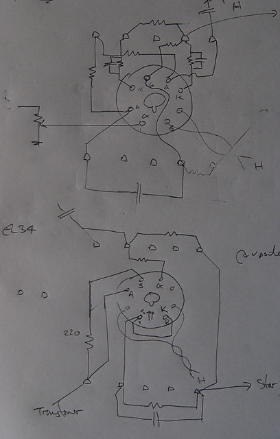
I don’t really know how other people do it, but drawing up a layout is something that I like to do with a notepad and paper. The tube pinout needs to be looked up – the Duncan Amps TDSL (Tube Data Sheet Locator) is a great resource for this. The pinouts are shown from the bottom of the socket, so the same as what you need for the layout diagram.
I do a rough sketch of the tube sockets and an anticipated useful number of terminal strips, and work through the circuit diagram trying to find a layout that fits well with the tube socket and nearby terminal lugs. Usually it takes quite a number of goes (redrawing the sockets each time) to get a good layout – this time, since I started with Earle’s layout from the photographs, it only took two.
Here is my component layout for one channel. This is a “doctor’s handwriting” layout – nobody but me is supposed to be able to understand it (not least because the tubes are reversed top to bottom and the EL34 layout is drawn upside-down):
(Click on photos to enlarge.)
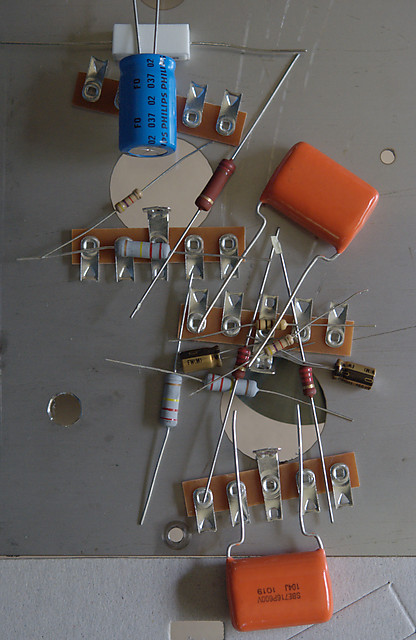
Then I placed the components around the holes for the tube sockets to check that the sizes and general arrangement would fit as I expected. Here is how it looks – again, this is for me to confirm the layout I had drawn, you shouldn’t expect to learn anything specific from this example: